Implementation of a High Performance
Low Cost PTP Clock
Introduction
The transition from a circuit switched to a packet based network data sometimes requires mechanisms for the transmission of precise time for synchronization of embedded systems as this information is not available any more. The femtocell, a thin 3G or 4G base station for indoor use and with a target price of less than $100, is an example of a device where this needs to be done at low cost.
This article is an introduction to the IEEE 1588 Precision Time Protocol, PTP. The article gives an overview of PTP basic principles and details of how hardware accuracy enhancements can improve accuracy by orders of magnitude. The use of a position integral (PI) servo loop (with some non-linear modification) in the PTP Protocol Engine software will allow for a nanosecond time resolution in spite of the jitter caused by packet switching.
About PTP
PTP is independent of network technology, but assumes that the average path delay between nodes is equal in both directions. The Protocol Engine will automatically adjust for this delay and will tolerate changes of the delay caused by network reconfiguration. We assume that TCP/IP over Ethernet used.
Grandmaster and Best Master Clock Algorithm
In a PTP network a Grandmaster (GM) is the node that defines what is the correct time. A GM normally has a highly stable oscillator and can have its clock locked to a built in GPS receiver or other time source reference. Thereby all clocks in the network can synchronize to a common reference such as TAI or UTC, which may be of value for legal and other reasons. In some applications a local time reference may be sufficient, eg. in a group of machines without any critical coupling outside the group. There may be several potential GMs in a PTP system, and the Protocol Engine software contains a mechanism, the Best Master Clock algorithm, that enables the clocks in the network to agree on the selection of the GM.
Frequency Synchronization
Sometimes the speed of the clock, i.e. the frequency, is more important than time. PTP can here be used to accurately and at low cost keep a frequency at a nominal and stable value for synthesis of the correct radio frequencies in a radio base station.
PTP Algorithms
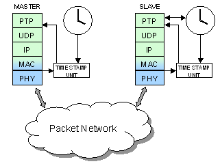
The standard describes how synchronization is done by the exchange of different messages between master and slave. The messages are described below (see fact box) with a diagram showing the interdependencies between the messages. Each message is a UDP packet, encapsulated in an Ethernet frame. Time stamping is done for some messages. Software in the slave performs the necessary computations, filters the phase and frequency error signals and adjusts the slave clock so the errors are kept within narrow tolerances. The algorithms must be such that the time to lock is short enough (usually less than a minute), but when steady state has been reached, the servo can utilize the fact that the source is very stable and the only source of error to neutralize (when the jitter has been averaged out) is the relatively slow inherent drift of the local clock.
Different PTP clocks
Until now we have only talked about when a slave or a master running the PTP stacks. The standard refers to these end node applications as Ordinary clocks. However, in a networked topology the there are also intermediate units. A PTP slave can also be a master for another slave and such clock is called a Boundary Clock (BC). A BC has a network port with slave functionality that controls a local clock and has one or more ports with master functionality that distributes the local clock’s time instead of forwarding PTP messages between its slave and master ports.The BC clocks are usually combined with normal switching functions.
With the version 2 of PTP yet another type of clock called Transparent Clock (TC) was introduced. A TC can replace a BC in network elements. A TC does not have its own clock, and it does not block PTP messages between the master and the slaves. However, it inserts data on its delay (residence time), and slaves “downstream” can take that into account in their computations. The residence time can be accumulated over several nodes, so a slave can adjust for the aggregated time delay in a chain of TCs.
Timestamped Messages Synchronize the Clocks
The synchronization is done by the exchange of four different PTP message types between master and slave as shown in the figure.
- Sync - This is a message from master to slaves, normally multicast. It is timestamped by both master and slave. It is sent at a sufficiently high frequency, e.g. once every second. The slaves timestamp the arrival and use these timestamps mostly to measure the frequency error, i.e. they calculate the time difference between successive sync messages according to the local slave clock, in order to compare that difference with the time difference observed at the master.
- Follow_Up - This is also a message from the master. It follows immediately after a Sync message and contains in its payload the master’s timestamp for the sync message. The slave needs these timestamps for the calculation of the time difference mentioned above, but now measured with the master’s clock, and can thereby calculate the error in the slave clock’s frequency. This error is processed in order to arrive at a suitable correction, drift adjustment, of the frequency of the slave clock.
- Delay_Req - This is a message from a slave to the master, sent at a lower frequency than that of the Sync and Follow_Up messages. It is timestamped by both slave and master.
- Delay_Resp This is sent from the master to a slave, as a response to the Delay_Req message from that slave. It transfers the master’s timestamp of the Delay_Req message. The slave can now calculate the apparent delay from slave to master. If the clocks are not perfectly synchronized the result will be affected by an error equal to the difference in phase between the two clocks. However, the corresponding calculation of the delay from master to slave, using the Sync message timestamps, will contain this same error but with opposite sign. Thus, by adding these calculated delay times together the errors cancel, and the sum is twice the actual delay time (provided it is the same in both directions). The servo software strives to advance or slow the slave clock until the delay time measured for the sync messages is equal to this calculated actual delay time.
A fifth type of message is the management messages used for other communication needed between PTP nodes.
Qulsar's Ordniary Clock implementation

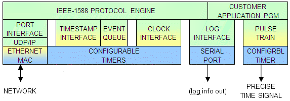
The block diagram illustrates roughly the organization of the system and how it is implemented. Green color is used for software, yellow for microcode, and blue for hardware. The customer application program can be developed in ANSI C, using the Conemtech Developer IDE. The platform has a POSIX compliant RTOS, a flash file system, and several I/O interfaces in addition to Ethernet channels.
The Conemtech processor architecture is built on extensive use of microcode – internal very low level, high speed, control code with wide microinstructions controlling the operations of every cycle with extreme flexibility in the combination of operations. Part of the microcode is writable, i.e. “soft” as software, which is unusual.
For accessing the network, the Conemtech processor chip contains an Ethernet MAC, implemented partly in microcode and partly in on-chip logic.
A clock should basically have a high frequency oscillator and a counter, with adjustable frequency and phase (i.e. time). In the Conemtech system system the local PTP clock can be adjusted without actually changing the oscillator frequency or the high-frequency counter. This will be described below.
Timestamping

High precision can only be achieved if timestamping is performed in hardware, close to the physical layer, so that the jitter caused by software is eliminated. A pulse is generated in the MAC logic at a specified point in the Ethernet frame passing to/from the physical layer, and this event triggers the copying of a counter value to a register.
Further timestamp processing is performed by interrupt-driven dedicated microcode – by the same processor core that also executes the TCP/IP stack, the RTOS, the PTP Protocol Engine, and typically some customer application – and thus requires no additional dedicated hardware.
On-chip timers
An on-chip configurable 8-channel timer system is used for the high-frequency timer and timestamp register, as well as for producing, under microprogram control, precise time signal output for use by embedded system hardware external to the chip.
Adjusting speed and phase of the local clock
A high-frequency oscillator drives a counter, but neither the oscillator nor the counter is adjustable. This counter measures “raw time” at the slave.
In the Ethernet MAC logic, the passage of the SFD byte to or from the PHY is detected. This event triggers the copying (capture) of the raw time counter contents to a register, and a microprogram IRQ is generated. The microprogram reads the register, as well as a continuation (more significant part) of the raw time counter that it keeps in its scratchpad, and stores this raw timestamp in a queue. However, it first checks that it is a PTP frame, or the timestamp is discarded.
When the raw time counter passes zero, it generates a microprogram IRQ, which triggers the microprogram to increment the continuation in the scratchpad.
Before the timestamps are delivered from the queue to the PTP software, they are converted to precise time according to the slave clock – which is virtual. The conversion is done by multiplication with a parameter A and addition of another parameter B.
The same conversion is done every time the software needs to read the current value of the precise time.
As mentioned above, the servo loop does not control the frequency or phase of the hardware counter. Instead it controls the parameters A and B. The actual slave precise time is not visible anywhere unless when it is calculated, which is only when needed. This saves energy.
Application example: Precise output signals

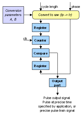
In typical applications external hardware needs precisely timed signals, e.g. a pulse train, from the slave clock. The configurable counter system is used also for this purpose. As an example, a transition on an output port pin at a given precise time is generated as follows:
- The desired event time is converted to raw time, most significant (ms) part and least significant (ls) part.
- The counter runs synchronously with the raw time counter. The ls part is loaded into a coincidence register (normally used for PWM), and the ms part is compared with the raw time continuation in the scratchpad. This comparison is done every time the raw time counter requests interrupt at zero.
- When the ms part agrees with the ms part of the raw time, then the output transition is enabled to occur at the next hardware coincidence.
-


