Femtocell Synchronization
The femtocell represents the smallest cell defined at present (2011) of the cellular network. It is normally related to the 4G technologies WiMax or LTE, but is also used in relation to the 3G networks. For the purpose of this application note the following description can also represent the picocell level of hierarchy. The different business models used for the two are not important here. One should however remember that the picocell often carries a higher payload on the Ethernet due to its higher capacity in terms of simultaneous users. The M50 is designed to handle a radio traffic payload of up to 60 Mbit/s in a Fast Ethernet network using the feed-through mode. If higher data rates are required a simple three-way switch can be inserted in the Ethernet path. However, the benefit of using just one IP address for the base station is lost as the PTP and Wireless processors will receive different IP addresses from the server with this setup.
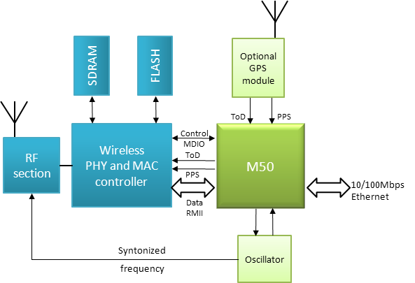
Figure 1 below shows how the M50 connects in between the wireless base band processor and the Ethernet port of the femtocell. Due to the high requirements on timing accuracy and frequency stability and the complex network of its deployments, the monitor and control of the M50 and its network loop controller will be assumed either by a centralized control or by the host processor in the femtocell, the wireless baseband processor.

Figure 1: M50 in a femtocell application
In figure 1 an optional GPS has been added. A GPS can be found in many of the first prototypes of femtocells which have appeared on the market. GPS will probably still be used for the outdoor mounted and more expensive units. The M50 features a standardized GPS interface and can be introduced to create a 1588 timing source backup in the event of a satellite black-out.
This integration corresponds to the integration level B of the Qulsar Integration Levels. The M50 is defined as a subsystem to the wireless controller. The femtocell is a cost sensitive application and the M50 is therefore designed to be booted by the wireless controller making it possible to save cost by not mounting a flash on the M50.
The M50 can provide a syntonized reference frequency of 5/10/20/25 MHz (selectable) feeding the radio of the cell. The RF section contains converters and filters to correct carrier frequency.
The M50 schematics for this application can be seen in figure 2. Two input signals, PPS and ToD, provides the reference timing information from GPS as long as it has a high quality reception (able to see enough satellites). When the GPS signal is lost, the M50 switches over to use the network based grandmaster as the time source.

Figure 2: Femtocell schematics for M50
For typical consumer in-door applications the 1588 synchronization will be used thus lowering the synchronization costs considerably versus the GPS or very precise local oscillator alternatives.
The on-module crystal is optimized for low cost and for a master tracking operation. If the network connection is lost in this application, there is no need for holdover in the cell as the data path is closed. The M50 can deliver only short range holdover to shut down calls in a controlled way. If the system setup however is different and the cell should maintain intra-cell calls, an external oscillator of choice can be added to the schematics. The M50 automatically senses the existence of such an external oscillator.
-


